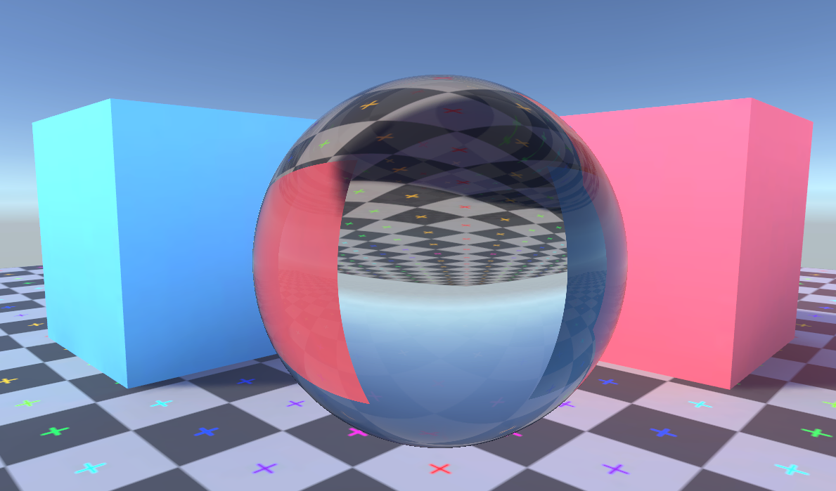
A classic demonstration of ray traced rendering is a distorted image caused by refraction. The effect can be reproduced without needing the expense of ray tracing through the whole scene. Just as reflections on glossy surfaces can be approximated by sampling a cubemap of the surrounding scene, we can do the same with refraction.
When the fastest thing in the universe slows down
You might have heard the speed of light talked about as a constant, but more accurately it's the speed of light in a vacuum that's constant. Light travels slower through other materials and that change in speed can cause a change in the light's direction, called refraction. The distortion when looking through curved glass or the bend that appears in a straight stick when it's partially underwater are both caused by refraction.
When going from a higher speed medium to a lower speed medium, light bends towards the surface's normal. Likewise going from lower speed to higher speed bends light away from the surface's normal. We call the surface where two mediums meet an interface. It can be useful to think of one side of a wave crossing the interface first, forcing the wave to change direction to adjust to the difference in speed over its width.
How much slower light travels in a medium can be represented by that medium's refractive index. By
definition vacuum has a refractive index of exactly 1. Glass has a refractive index of about
1.52, meaning the speed of light within glass is c ÷ 1.52. That's a significant
reduction in speed! Air has a refractive index of around 1.000293, and so long as no physicists
are looking you can pretend it's 1. You'll notice some "about"s sprinkled in there, that's
because the reflective index varies with things like pressure and humidity. This is what causes visible heat
haze effects above very hot objects.
The refractive effect is also different depending on the light's frequency. This is what causes dispersion, where a beam of white light can be split into its component colours due to the different frequencies getting refracted by different amounts. As is often the case how many of these effects you want to model, fake, or ignore in your rendering systems is up to you.
Air to glass
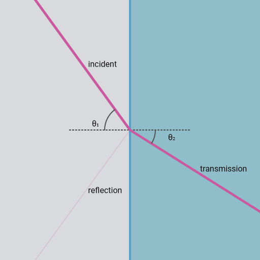
The above diagram is a simple simulation of a light ray moving from the air on the left into a glass block on the right. Click (or touch) on the left area to change the angle of the incident ray. At the interface of the two mediums its speed changes, and unless it hits the surface straight on that will cause its transmission path to be bent.
How much the transmission ray is bent away from the incident ray's path is determined by Snell's Law.
Where η₁ is the refractive index of the medium on the incident side; θ₁ is the angle between the surface normal and the incident ray; η₂ is the refractive index of the medium the ray is entering; and θ₂ is the angle between the surface normal and the transmission ray on the other side of the interface.
You can also see some of the light doesn't get through the interface and is instead reflected off back into the air. How much is reflected instead of refracted depends on the refractive indices of the mediums and on the incident angle. Try moving the ray so that it is almost parallel to the surface and you'll see almost all the ray is reflected. This increase in reflection at grazing angles is commonly known as the Fresnel term in lighting equations, and a simplified form (without refractive indices) is often used when rendering opaque objects.
Glass to air
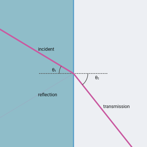
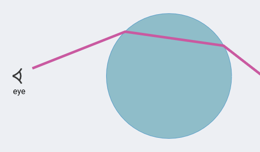
A ray going from a higher refractive index medium to a lower one follows the same rules, but there's a special case we need to consider. Because the exit ray is rotated away from the surface normal it's possible for the exit angle to be calculated as above 90°, but that wouldn't make sense for a ray that's meant to be leaving the medium. This case is called total internal reflection, and as the name suggests when it happens there's no refraction at all and instead the light ray is wholly reflected.
Because humans spend most our time in a low refractive index medium (air) we don't see total internal reflection as commonly as other effects of refraction. If you've looked up when underwater and seen that the water's surface appears mirror-like then you've seen total internal reflection. On a smaller scale you may be able to see it when peering into a glass of water from certain angles if the container is shaped correctly.
Follow that light ray
The basic principle of ray tracing is that you create a ray (or several) for each display pixel and follow it through the scene to work out what colour that pixel should be. Generally this is slower than the rasterisation techniques normally used in real-time graphics. So rather than doing it for the whole scene we'll be doing it just for one object that we want to have pretty refraction effects. We'll follow the ray from the eye through the object, but once the ray leaves the object instead of tracing what other objects or lights it hits in the scene we'll just sample a cubemap representation of the surrounding scene.
Spheres are firm favourites for ray tracing because they're simple to define mathematically. The surface of a sphere is where the distance from its origin is equal to the sphere's radius. How far is a point from the sphere's surface? Find the distance to the sphere's origin and subtract the radius. What's the surface normal at a point on the sphere? Just take the vector from the sphere's origin to that point and normalize it.
The actual mesh that we render with doesn't need to be a sphere, all it needs is to cover the area where we want the sphere to appear. Let's use the example of a simple cube and see how we'd design a shader so that a sphere appears within it.
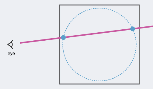
You can click (or touch) the diagram above to change the ray's direction. The box represents the surface of the mesh, with the sphere we want to draw floating within. We can do a bit of maths to find when the ray will touch the sphere's surface, with the resulting positions from that shown as dots in the diagram.
I find it convenient to think of rays as being like a particle that moves through the scene (the ray actually moves instantly, "time" is just a nice way to reason about how the ray travels.) We can call its starting position s, its velocity v, which means its position at time t is:
For convenience we'll use the sphere's center as the origin point, meaning postions are given relative to there. So the ray hits the surface of a sphere with radius of r when:
From the Pythagorean theorem we know how to find the length of a vector:
We can square both sides to get rid of the square root, and sub in for rayPosition:
A bit of multiplying out and rearranging we end up with this quadratic for t:
This can be solved using the quadratic equation. We'll get no solutions when the ray misses the sphere entirely, two identical solutions if the ray perfectly skims the sphere, and two different solutions when it passes through the sphere hitting the surface on the way in and the way out.
Sphere in a shader
With the maths sorted out for ray-vs-sphere we can make a shader using it. The principles here apply to any system but we'll demonstrate it in Unity's universal render pipeline (URP) and the shader graph system.
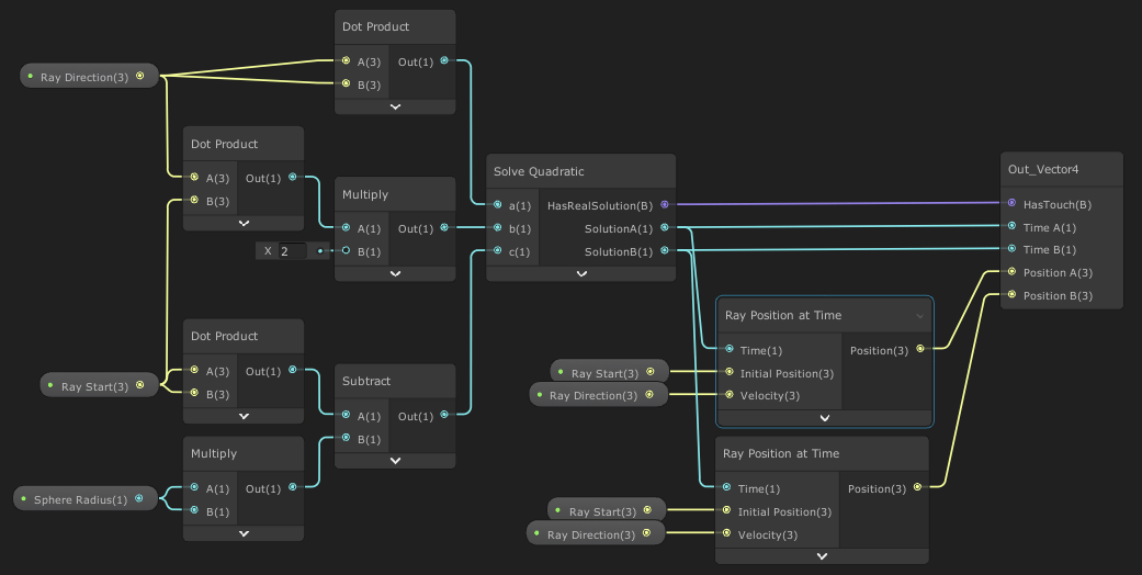
This subgraph is the heart of the shader. You can see how the a, b, and c values are prepared to be fed into the quadratic solver to find the "time" when the ray will hit the sphere's surface. The solutions are then used to get a position for each intersect.
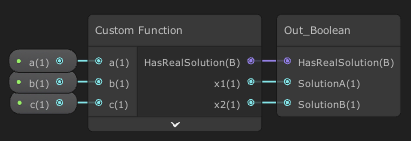
The solve quadratic subgraph is just a wrapper for a custom node. The function could be expressed in shader graph nodes, but I find it adds needless complexity for what's fairly simple when expressed in code:
float s = sqrt(b * b - 4 * a * c);
HasRealSolution = s > 0.0 && a != 0.0;
x1 = (-b + s) / (2 * a);
x2 = (-b - s) / (2 * a);
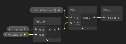
Ray position at time is calculated simply enough and just as you'd expect. Having even simple operations like this put into a subgraph will save a bit of time and more importantly makes it clearer what's going on within a complex graph.
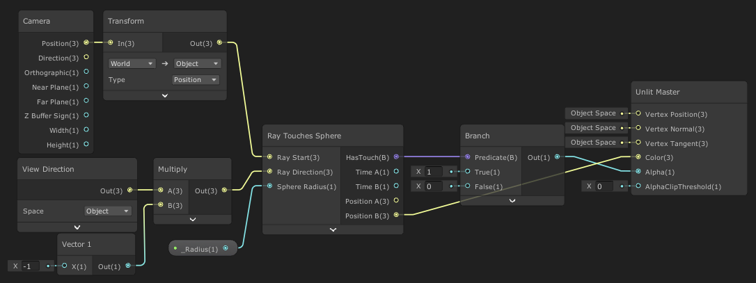
Finally, here's the actual shader graph. Notice that both the camera position and the view direction are in object space, meaning they'll be given in terms relative to where the object in the scene is. That means a position of (0, 0, 0) will be in the center of our sphere. We flip the view direction vector because the node gives us a direction from the fragment towards the camera, but our ray should be directed out of the camera. Speaking of which, we have the ray's initial position set to be the camera but it works just as well to use the fragment's position on the surface of the mesh.
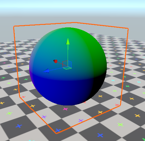
The output is hooked up to represent the position of the ray intersection closest to the camera. You can see how the surface is more blue in the +z direction and more green in the +y direction. This is a screenshot from within Unity's editor, with a glowing orange outline around the cube mesh that's actually being rendered. The appearance of a sphere is thanks to our shader, not the mesh.
You might also notice we could have just used a sphere mesh and rendered it with a far simpler shader to get a very similar output. The point of all this is that we'll be able to use the same technique to know how any arbitrary ray would hit the sphere, not just one coming straight from the camera.
Through the looking-sphere
Again you can click (or touch) this diagram to change the ray's direction. By combining our understanding of how refraction bends light rays and how to perform ray-vs-sphere collision, we can now trace a ray as it gets refracted through a sphere. For simplicity this diagram ignores reflection and just shows the part of the ray that will get refracted.
There are a few interesting properties you can notice here. A ray directed straight at the sphere will pass through unbent. The change in angle as a ray enters is exactly the same as the change as it leaves—this is a property particular to spheres. Because of that relationship between entry and exit rays total internal reflection can never occur in a sphere with a higher-than-surroundings refractive index.
Our shader is already finding the position on the sphere surface where the ray from the eye intersects, we can combined with with the surface normal and the material's index of refraction to find where the refracted ray will go. You'll recall from earlier that finding the normal of a sphere is wonderfully simple.

So long as we're working in object space with the sphere at the origin of that space it's just a case of normalizing the position vector. If the sphere were offset from the origin it just takes a subtraction to properly offset the position vector.
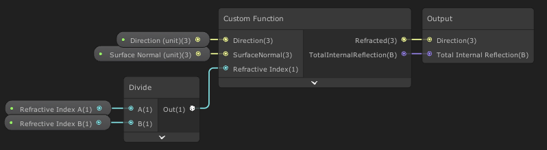
Usefully HLSL has a built-in refract function so we can just wrap that up in a custom node. To
handle the total internal reflection case, the built-in function returns (0, 0, 0). Our
wrapping node can detect that and provide a boolean:
Refracted = refract(Direction, SurfaceNormal, RefractiveIndex);
TotalInternalReflection = (Refracted == float3(0.0, 0.0, 0.0));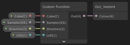
Unity's shader graph provides a Sample Cubemap node but it's set up to reflect the direction vector you give it. Although we could work around that, it's simple enough to wrap a custom function and make our own cubemap sampler:
Out = SAMPLE_TEXTURECUBE_LOD(Cube, Sampler, Direction, LoD);

With these new parts we can finally make our sphere refract some rays.
Following the flow through this graph from the left, we start by finding where the ray hits the sphere. That position is used to find the sphere's normal. That normal is used to refract the ray. We then find where that refracted ray will next hit the sphere. Again we find the normal at that point, and refract again. We take that direction and after transforming it into world space we sample a cubemap representing the scene that surrounds our object.
We have followed a single ray from the eye through this glass sphere, and found what direction it ends up pointing. We look up what colour the surrounding scene is in that direction and display that.
The Scene Cubemap
Something you might notice is that the position our ray leaves the sphere isn't taken into account when we decide what to display. This is not true to life, but is hard to avoid when using a single cubemap to represent the surrounding scene. The cubemap gives us a view of the scene from just one position and all we can do is pick which direction we want to sample. (Depending on the layout of the surrounding scene, the "box projection" method may be useful to partially account for the ray's exit position.)
It's very common to approximate a surrounding scene using a cubemap when handling reflections on glossy surfaces. In both that case and this only the direction is used and the results are widely accepted. The cubemap method is closest to reality when the rest of the scene is far away from the refracting object and the refracting object is relatively small.
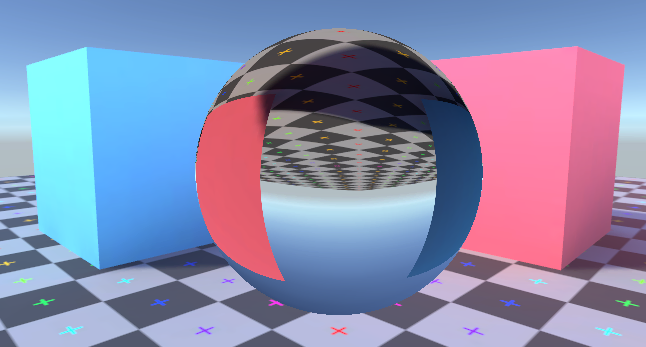
Our refraction method misses out on a noticeable property of how spheres refract light in reality. If an object is close enough to a glass sphere it will appear distorted but the correct way up. The image of an object should only flip once it has moved a certain distance away. With our cubemap sampling approach that effect is lost and the image through the sphere is always flipped.
As with reflective objects you'll get the best results if your cubemap is placed close to where the refractive object is. In this case I've simply placed a Unity reflection probe at the origin of the mesh used to render our glass sphere. As with all use of reflection probes keep in mind that constantly updating it can be costly with regards performance, increasing with the probe's resolution and number in the scene.
Adding Reflection
Speaking of reflections, we've neglected to deal with the ray being partially reflected when entering the sphere. A ray passing through an interface between mediums with different refractive indices should always be split into two parts. The refracted ray will pass through the interface into the new medium with a changed direction, the reflected ray bounces off the interface back into the medium it entered from. How the colour from these two rays should be mixed is decided by the reflectance value from the Fresnel equation.
To start with let's just handle the external reflection when the ray first enters the sphere. Unity's shader graph already has a reflect node and we already have the incoming ray's direction together with the sphere's surface normal. But we do need to do some Fresnel-related calculation to know how strong the reflection should be.
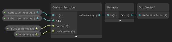
The full Fresnel equations for what happens to light as it passes from one medium to another are complex and deal with things like the polarisation of light (which we're just ignoring.) Instead we can use the Schlick approximation. This gives us a nice reflectance value between 0 and 1 telling us how much priority should be given to the reflected ray. It also deals with total internal reflection, setting reflectance to 1 when that's encountered.
// approximation of the Fresnel equation for reflectance
// based on https://graphics.stanford.edu/courses/cs148-10-summer/docs/2006--degreve--reflection_refraction.pdf
float r0 = (n1 - n2) / (n1 + n2);
r0 *= r0;

float cosX = abs(dot(normal, rayDirection));

if (abs(cosX) < 0.0001)
{
    reflectance = 1.0;
    return;
}

if (n1 > n2)
{
    float n = n1 / n2;
    float sinT2 = n * n * (1.0 - cosX * cosX);

    // detect total internal reflection
    if (sinT2 > 1.0)
    {
        reflectance = 1.0;
        return;
    }

    cosX = sqrt(1.0 - sinT2);
}

float x = 1.0 - cosX;

// chained multiply is (probably) faster than pow(x, 5)
reflectance = r0 + (1.0 - r0) * x*x*x*x*x;
Although this is very close to physically accurate don't be afraid of adding in the ability to arbitrarily adjust things. Providing a slider whose value is added to this reflectance value makes tweaking an asset to get the right look far easier. Even if your goal is to make images that look real, that's not always the same thing as them being totally physically accurate.

This reflection handling is added into our existing shader graph. A Lerp node blends between the view from the reflected ray and the view from the refracted ray depending on the calcualted reflectance value.
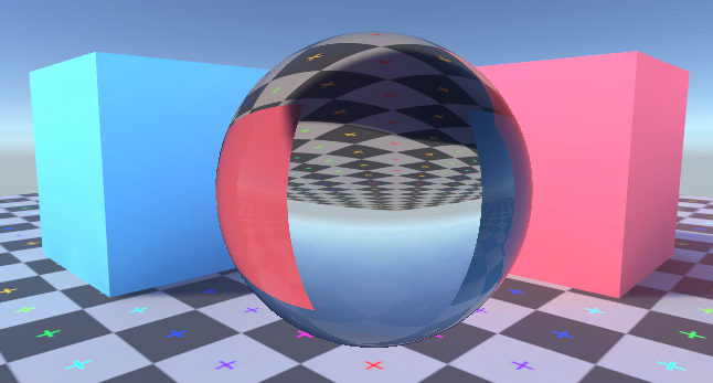
The addition of a surface reflection goes a long way to help the sphere feel like it's part of the scene.
Internal reflection
When a ray leaves our sphere it should be split in two, with one of those being reflected back into the sphere. That ray will hit the sphere again somewhere else, where it again should be split in two with one reflected back into the sphere. That pattern continues forever and for each bounce the reflected ray is contributing less to the final displayed colour. We can decide on some number of bounces to trace before assuming the result is close enough to reality.
To model the many internal bounces in our shader let's put the process for tracing the ray into a subgraph that we can repeatedly use.

Given a ray, the sphere's radius (with the assumption the sphere's origin is at (0,0,0)), and
the refractive indices of the mediums, this finds where the ray will exit the sphere and the direction of
the reflective and refractive rays that it'll split into, as well as the reflectance value used to mix the
colours from the rays. We can repeatedly use this subgraph to trace multiple bounces around the inside of
our sphere.

The first use of the subgraph is following a ray after it enters the sphere, with the position it tries to leave the sphere and the reflected direction used to trace another ray. Each iteration leads to another sampling of the scene cubemap for the split off ray that exits the sphere. It's easy enough to repeat this process as many times as we like, but with the awareness that each iteration is going to increase the rendering cost. Let's try out a few different iteration counts.
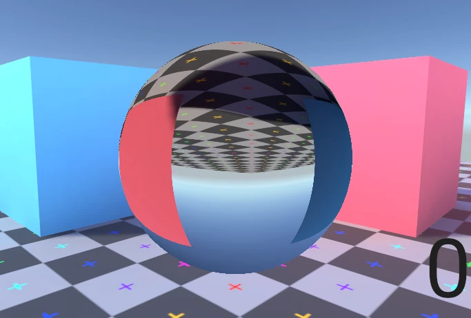
You can see that each additional bounce changes the final image less than the previous one, despite causing the same increase in shader complexity. There's obviously a balance to be struck here.
Summary
We've gone through a basic introduction to both the principles of ray tracing and refraction. By understanding the mathematics of how a ray is affected by passing through the interface between two mediums we've been able to create a shader that traces rays through a sphere and out into the surrounding scene. We've seen that we can use a cubemap to represent the surrounding scene as an alternative to needing to trace the ray through the whole scene (with some caveats about its accuracy.) Putting that all together we made a scene that looks straight out of a rendered computer graphics image from the late 1980s.
There's a lot of room to expand from here! The material of this sphere currently isn't absorbing or scattering any light, and there's no dispersion causing colours to separate. The techniques used here can also be extended to handle shapes which aren't just spheres. I plan to cover at least some of these in the near future. I'm particularly pleased with a technique to approximate refraction through an arbitrary convex mesh.
The example project can be downloaded directly as a .zip or found on GitHub. As usual with Unity projects you'll need to do a little ritual after downloading. When you first open the project it'll take a few minutes to build the local library. You'll then need to Open Scene to open the actual sample scene in the project (Unity silently generates a default start scene and shows you that instead.) To be safe you may need to restart Unity too.