This is a continuation from a previous article on raytracing through a sphere. That shader dealt with the path of rays passing through a transparent sphere, but didn't account for the material of the sphere absorbing any of the light. Here we'll explore how to simulate that effect so that the sphere itself can take on a colour.
Removing Light
Although passable results could be achieved by just tinting the output from the original shader, let's continue to examine how light behaves in the real world and apply that to hopefully get more realistic results.
As light travels through a medium some of it will be absorbed. Pure water doesn't absorb much light, while prepared tea strongly absorbs certain wavelengths causing the light that makes it way through to appear a different colour. For our purposes we're not too worried about exactly how that absorption happens—it has to do with matching energy levels in molecules—but what is important to us is that absorption is always about certain wavelengths of light being reduced.

If you shine a white light through tea, light with an yellow-orange hue comes out due to greater absorption of wavelengths corresponding to the blue end of the spectrum. If we shine a blue light through tea it would be darkened but not turned orange. Absorption reduces the intensity of certain wavelengths, it doesn't increase the intensity of any, nor does it convert one wavelength to another.
Red green blue
When handling colours in computer graphics we usually deal with them in terms of the primary colour
components red, green, and blue. You'll be familiar with how we can make white by setting them all to full,
or turn up just the green and blue to make cyan. This is analogous to how real light is made up of a range
of wavelengths. When our tea absorbs blue wavelengths it's like taking a white colour
(1.0, 1.0, 1.0) and subtracting the absorbed blue-ish wavelengths (0.0, 0.3, 1.0),
to make the tea's transmitted yellow-orange colour (1.0, 0.7, 0.0).
Real light isn't just a mix of the three primary colours, instead it's a spectrum of different frequencies
each with their own intensity. These can be represented as a spectral curve showing the variation in
intensity of light across wavelengths. You could have two light sources that appear yellow, one with a high
intensity around 580nm (yellow visible light), the other with spikes in intensity around 540nm (green) and
700nm (red). Both would be represented in most computer graphics as something like
(1.0, 1.0, 0.0) but in reality would cause subtly different lighting effects on some surfaces
and through some mediums.
For the most part these differences aren't large enough to be noticeable, so it's typical to simulate light as simply being a mix of red, green, and blue. But it's always good to be aware of the shortcuts we're taking.
If you've ever changed what type of light bulb is used to illuminate a room and found that although the bulb is classed as the same colour everything looks a bit different, that may be due to differences in the spectral curve. Flourescent lights especially tend to have "spiky" curves. The light can be designed so that the spikes add up to the same warm orange as an old incandescent bulb but the gaps between the spikes create subtle changes in how the light behaves. Fortunately LED lights are very good these days with increasingly many models providing smooth spectral curves, using much less energy than incandescent bulbs, and lasting longer.
Absorption over a distance
As you might expect the further light travels through a medium the more of the light will be absorbed. But it's not a linear relationship. Graph generated with the always useful Desmos graphing calculator.

This relationship is from the Beer-Lambert Law, although as with many other laws of optics we're really only interested in a part of it. We'll replace all the fancy stuff about solution concentrations with a simple "absorption coefficient" property. In this case we're just interested in the relationship between how much light is transmitted through a medium and how far the light had to travel through that medium:
Combining this with our understanding that light absorption can be simulated by reducing the value of individual components we can put together a shader subgraph.

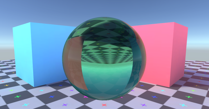
Absorbant Volume
By reusing the ray-vs-sphere subgraph from a previous article we can create a simple effect of a sphere that absorbs light passing through it.

To get the path length we take the distance between the two points where a ray from the camera intersects the sphere. For a base colour value we use the scene colour (provided by the Universal Render Pipeline so long as we enable the opaque texture option.) The absorption effect is applied to the scene colour and simply passed as the output colour for the shader.

Absorbant Rays
We can also integrate absorption into the refraction and reflection shader we made during that previous article.
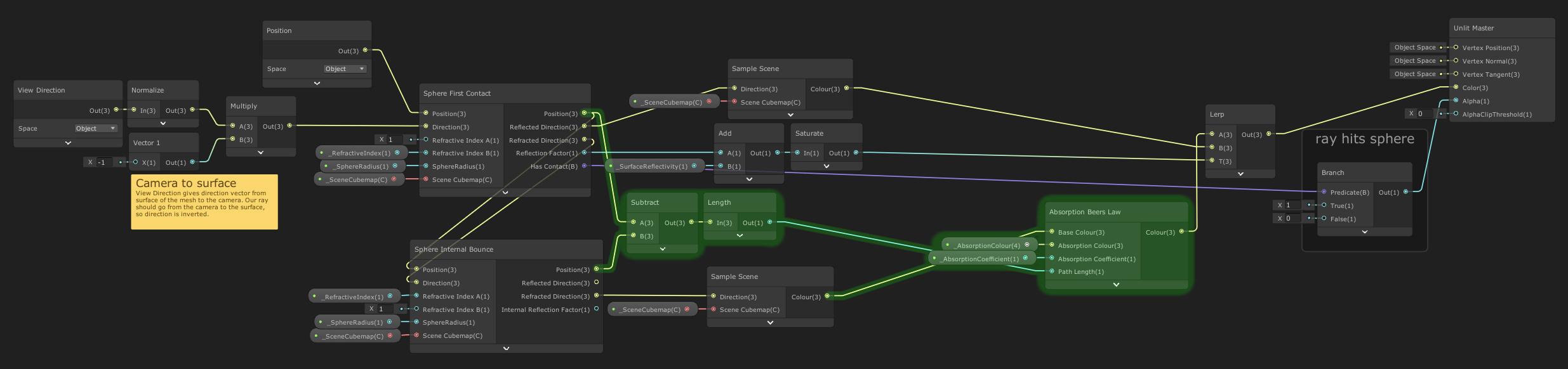
This first graph is a simplified version of the shader with no internal reflection bounces to keep it relatively straightforward to read. The additions for handling absorption are highlighted in green.
In this case the only absorption is when the ray is passing through the sphere from the entry point to where it exits. We subtract one of those points from the other and find the length, giving path length through the medium. That's fed into the absorption subgraph along with the colour that the ray ends up sampling from the scene. Notice that the colour from the ray that's reflected off the sphere's surface isn't affected by absorption, as that ray never passed through the absorbing medium.
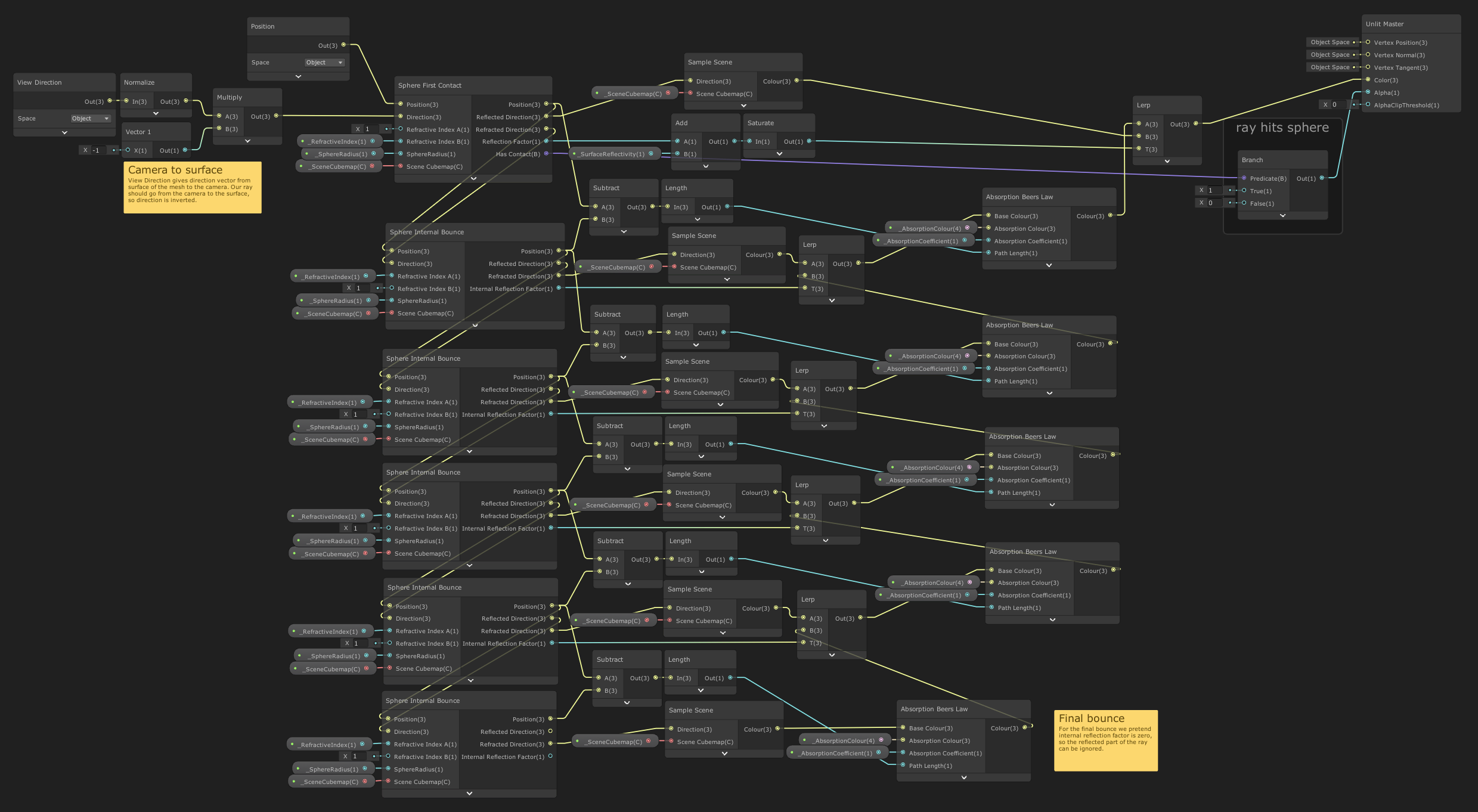
You can see why I demonstrated it in a simpler shader graph first. Although this is larger and looks more complex, it's really just the same operation being done repeatedly. For each passage through the sphere we find the path length and apply absorption based on that. Notice that the colour sampled down at the bottom of the graph ends up passing through absorption multiple times, this reflects how that ray is bouncing back and forth through the sphere multiple times, undergoing additional absorption each time.
Selecting Colours
Because absorption removes wavelengths from light, we specify the absorption in terms of what colour the
medium absorbs rather than what colour the transmitted light will be. So if you want the sphere to look red
you should set the absorption colour to be the "opposite" colour, something around
(0.0, 1.0, 1.0). When using a colour wheel you'll notice this is on the opposite side of the
hue circle.

In reality it's rare for a medium to leave any wavelength of light totally untouched by absorption, so it's often good to pick an absorption colour that's not at maxium saturation. That way with a sufficiently long path length (or high absorption coefficient) eventually all wavelengths of light would be absorbed.

The example project can be downloaded directly as a .zip or found on GitHub. As usual with Unity projects you'll need to do a little ritual after downloading. When you first open the project it'll take a few minutes to build the local library. You'll then need to Open Scene to open the actual sample scene in the project (Unity silently generates a default start scene and shows you that instead.) To be safe you may need to restart Unity too.